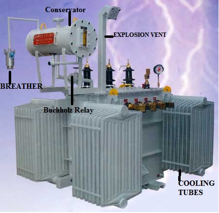
What Is a Transformer?
A transformer is an electrical device that transfers electrical energy from one circuit to another by electromagnetic induction (also called transformer action). It is used to step up or step down AC voltage.
Components of a Transformer
1) Laminated core
2) Windings
3) Insulating materials Transformer oil
4) Tap changer
5) Oil Conservator
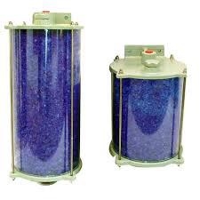
6) Breather Cooling tubes
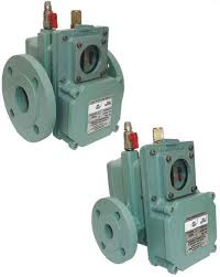
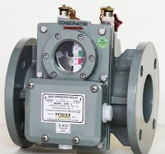
7) Buchholz Relay
8) Explosion vent
Of the above, laminated soft iron core, winding’s and insulating material are the primary parts and are present in all transformers, whereas the rest can be seen only in transformers having a capacity of more than 100KVA.
Of the above, laminated soft iron core, winding’s and insulating material are the primary parts and are present in all transformers, whereas the rest can be seen only in transformers having a capacity of more than 100KVA.
How Transformers Work
Basic Transformer Design It is important to remember that transformers do not generate electrical power; they transfer electrical power from one AC circuit to another using magnetic coupling. The core of the transformer is used to provide a controlled path for the magnetic flux generated in the transformer by the current flowing through the winding’s, which are also known as coils.
There are four primary parts to the basic transformer. The parts include the Input Connection, the Output Connection, the Winding’s or Coils and the Core .
Input Connections – The input side of a transformer is called the primary side because the main electrical power to be changed is connected at this point.
Output Connections – The output side or secondary side of the transformer is where the electrical power is sent to the load. Depending on the requirement of the load, the incoming electric power is either increased or decreased.
Winding – Transformers have two winding’s, being the primary winding and the secondary winding. The primary winding is the coil that draws power from the source. The secondary winding is the coil that delivers the energy at the transformed or changed voltage to the load. Usually, these two coils are subdivided into several coils in order to reduce the creation of flux.
Core – The transformer core is used to provide a controlled path for the magnetic flux generated in the transformer. The core is generally not a solid bar of steel, rather a construction of many thin laminated steel sheets or layers. This construction is used to help eliminate and reduce heating.
Transformers generally have one of two types of cores: Core Type and Shell Type. These two types are distinguished from each other by the manner in which the primary and secondary coils are place around the steel core.
Core type – With this type, the winding’s surround the laminated core.
Shell type – With this type, the winding’s are surrounded by the laminated core.
When an input voltage is applied to the primary winding, alternating current starts to flow in the primary winding. As the current flows, a changing magnetic field is set up in the transformer core. As this magnetic field cuts across the secondary winding, alternating voltage is produced in the secondary winding.
The ratio between the number of actual turns of wire in each coil is the key in determining the type of transformer and what the output voltage will be. The ratio between output voltage and input voltage is the same as the ratio of the number of turns between the two winding.
A transformers output voltage is greater than the input voltage if the secondary winding has more turns of wire than the primary winding. The output voltage is stepped up, and considered to be a “step-up transformer”. If the secondary winding has fewer turns than the primary winding, the output voltage is lower. This is a “step-down transformer”. se versa occurs.


